


 ‘Himmelhopper’ - Flying Foxes, Gondolas, Aerial Ropeways, Cable Cars, Passenger Conveyors, Passenger Ropeways.
Functional description for the control system for the passenger transport shuttle at the AJ HACKETT NEVIS BUNGY.
This document contains the information required to design and implement a control system for the safe operation of the passenger transport shuttle servicing the jump pod on AJ Hackett Queenstown Ltd's Nevis bungy site in Central Otago.
This shuttle is a reversible aerial passenger ropeway and therefore should comply with Part 8 of the Approved Code of Practice for Passenger Ropeways in New Zealand.
The Code is specific about how an aerial ropeway shall be controlled and this specification details the features and systems required.
The control system needs a high degree of integrity and in all instances shall be designed to fail to safety.
1. GENERAL DESCRIPTION
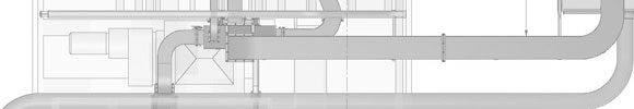
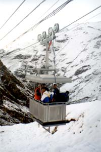
- The shuttle consists of a passenger cage which travels between a docking station on the north bank of the Nevis river and a jump pod which is suspended on four 32 mm diameter steel cables above the Nevis river. The cage is suspended on a four wheel bogie which runs on the upstream (west) outer cable. The cage is fitted with two doors, one on the east side for embarkation and disembarkation of passengers at the docking station, and one on the south end to facilitate access to the jump pod.
- A concrete counterweight is suspended on an identical bogie which runs on the downstream (east) outer cable. This counterweight is used to store the energy of the descending cage and passengers for use on the return trip. This will lower the overall power consumption of the drive system by up to 45%.
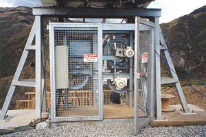
- The shuttle drive consists of two geared motors driving 720 mm diameter sheaves. The drive is situated on a self contained steel structure underneath the tower supporting the main cables on the north bank. These drives normally operate in tandem but each drive has the capacity to haul the shuttle if so required. The drives are normally powered by the main diesel electric generator on the site but can also be driven by a 5kVA standby generator set.
- The shuttle shall have two control panels; a lockable main panel at the docking station and a secondary panel on the pod. The shuttle shall be controlled using a PLC which may or may not be integrated with the inverter drive. In either case the PLC shall have facility for integrating its operation with a site wide PC based SCADA system at some time in the future.
2. CAGE SPEED CONTROL
2.1 Normal operation
2.1 Normal operation
- The cage speed shall normally be controlled by an inverter drive.
 This drive shall be sized and arranged to drive both motors, one forward and one reverse. A rotary encoder on Drive 1 shall be used to determine cage speed and cage position and provide the input necessary to give the required cage speed profile. Cage speed and position shall be provided as analogue outputs and displayed on the operator's panel.
- The nominal cage speed with the motors running at 50Hz is 1.92 m/s. The cage shall be allowed to run up to 240% over-speed during descent and ascent under the action of gravity or the counterweight.
- Provision shall be made for manually adjusting the cage speed but only to allow the cage to be driven slower than the normal speed profile. This manual control shall be key operated and located inside the lockable operator's panel.
- Provision shall be made for manual jog buttons to allow the cage to be jogged at low speed in both directions.
2.2 Backup systems
- The Code requires a minimum of three independent checks of cage speed (Clause 8.16.1.1(e)). The primary measurement of cage speed will be the rotary encoder on Drive 1. The second measurement of cage speed shall be made using the data supplied by a rotary encoder fitted to the electric motor on Drive 2. A proximity sensor shall be fitted to the counterweight wheel to provide the third independent check of cage speed. The signals from the encoder on Drive 2 and the proximity sensor on the counterweight wheel shall be processed independently by the PLC and used to verify the data from the encoder on Drive 1.
- In the event of either backup sensor detecting an over-speed situation (>1.92 m/s) when the cage is within 10 metres of the docking station or the pod, the cage shall be slowed to 450 mm/sec at an acceleration between - 0.5 m/s2 and -2 m/s2.
- In the event of either backup sensor detecting a speed in excess of 450 mm/s when the cage is within 2 metres of the docking station or the pod, the cage shall be stopped.
3. CAGE POSITION CONTROL
- In addition to the position control provided by the rotary encoders the docking station and pod shall be fitted with limit switches as follows:
1) two off wire actuated limit switches to detect the arrival of the cage at the docking station/pod
2) one off ski bar actuated limit switch to detect the presence of the cage at the docking station/pod
3) two off lever actuated limit switches to stop the cage at the correct position
4) one off emergency backup limit switch to stop the cage if the normal stop limits fail - The emergency backup limit shall be hardwired to cut power to the drive system and shall not rely upon the PLC to achieve this.
- Where two limits are fitted, only one shall need to be made to initiate the relevant response.
- The status of all of the above limit switches shall be displayed on the operator's panel and on a display panel in the pod. In addition to the limit switch status indication the position of the cage on the ropeway shall be indicated.
4. CAGE OPERATION
- An operator's panel shall be installed on the embankment which shall contain the inverter drive and all associated haul rope drive control equipment. This enclosure shall be IP65 rated. All analogue displays and indicator lamps shall be mounted in this enclosure behind toughened glass windows.
- Cage travel from the docking station shall be enabled by a staff member turning a key switch on the operator's panel. Cage travel shall be initiated by pressing a button situated on a pedestal adjacent to the north-east corner of the cage. The button shall be accessible from both the cage and the platform. An emergency lock-out stop button shall also be located on this pedestal. This lock-out stop shall be reset by turning off and on the key switch on the operator's panel.
- Cage travel from the pod shall normally be initiated by a staff member on the pod turning a key switch and pressing a button simultaneously. The cage shall not be allowed to leave the pod unless the pod door is closed and locked. An emergency lock-out stop button shall also be located on this panel. This lock-out stop shall be reset by turning off and on the key switch on the control panel in the pod.
- A push button shall be installed on the outside of the pod within reach of a person in the cage. A key switch on the panel in the pod shall transfer control to this push button. Pushing this button shall initiate the return of the cage to the docking station. At the end of the working day the pod staff can use this button to return to terra firma.
5. TORQUE MANAGEMENT
- The geared motor drive torque shall be monitored by the control system.
 The drive torque shall be indicated at the main operator's panel. The motors shall be shut down if the torque exceeds a prescribed limit. Lamps on the main operator's panel and the panel in the pod shall indicate this condition.
- The torque arms from each of the two geared motors will be connected to a balance beam. A limit switch on each side of this balance beam shall be used to detect excessive torque differential. These limits shall be installed in a normally closed state. In the event of either of these limits being opened the drive shall be stopped. The faulty drive can then be disconnected mechanically and electrically and allowed to rotate with the sheave until it can be removed and repaired.
6. COUNTERWEIGHT MANAGEMENT
- A limit switch shall be used to detect that the haul rope counterweight is approaching the bottom end of its travel. Closure of this limit shall bring up an alarm light on the operator's panel.
7. WIND SPEED INDICATOR
- An anemometer shall be installed on the pod to measure wind speed. The wind speed shall be displayed on the main operator's panel and on the panel in the pod. The wind speed shall be monitored and recorded by the control system and the cage prevented from attempting to dock with pod if the wind speed exceeds a nominated value.